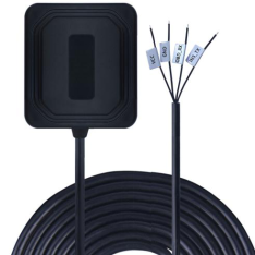
Product overview
| CE-GM-AGDR8639 is a G-MOUSE product composed of MCU main control, MTK series dual-frequency multi-mode high-precision GNSS chip, six-axis gyroscope inertial system and dual-frequency antenna. CE-GM-AGDR8639 Built-in multi-positioning system concurrent receiver module, support GPS, GLONASS, Galileo, Beidou and QZSS L1&L5 band synchronous reception. It has 75 tracking channels and 135 acquisition channels, enabling it to capture and track any multi-satellite mixed signal; Compared with a single GPS system, the number of satellites can be significantly increased by the multi-positioning system, which greatly reduces the first positioning time, and can achieve stable and higher positioning accuracy and accuracy even when driving in complex urban environments. The six-axis gyroscopic inertial navigation system can continuously achieve high-precision positioning in the environment without satellite signals (tunnels, underground parking lots), filter out the high-precision positioning drift (dynamic and static) caused by occlusion, refraction and reflection of satellite signals in the city canyons and trees, and constantly output data information such as vehicle driving posture and drivers' dangerous driving behaviors |
CE-GM-AGDR8639
Product application
AGV robot
Agricultural automation equipment
High precision vehicle navigation
Bus intelligent transportation
Vehicle remote monitoring

product feature
| uses high performance low power dual-frequency GNSS chip | |
| Support for multiple satellite systems: GPS&QZSS,GLONASS, Galileo, Beidou, dual frequency L1&L5 signal synchronous reception | |
| Ultra-high tracking sensitivity: | -167dBm |
| Supported protocol | NMEA-0183& Custom Inertial Navigation Protocol |
| Built-in six-axis gyroscope and gravity acceleration sensor allows users to define a variety of Angle and gravity algorithms | |
| Supports autonomous inertial navigation and positioning without GNSS signals | |
| Built-in high gain low noise amplifier | improve the receiving sensitivity |
| Working voltage | 3.3V~5.5V |
| Power consumption | 120±5mA |
| Operating temperature | -40°C ~ +85°C |
| Patch antenna dimensions | 35X35X4mm+25X25X4mm |
| Product size | :52.7±0.5x57.6±0.5x20.72±0.5mm |
| Cable interface type | 4-core bare wire, cable length 200cm |
| Communication method | UART |
| Waterproof grade | IP67 |
| RoHS certified products | |
performance specification
1.1 Product Features
Item | Peculiarity | Item | Peculiarity |
Gyro drift | High precision attitude heading information is obtained by eliminating gyro drift | Component selection | High performance three axis gyroscope and three axis accelerometer |
Acceleration noise | Eliminate vibration acceleration and obtain high precision speed information | Error compensation | Complete orthogonal error/temperature drift and other error compensation |
Zero speed correction | Zero speed correction algorithm can prevent navigation data drift | Unique anti-theft | Each product calibration parameters are inconsistent anti-piracy |
Software algorithm | Adaptive extended Kalman filter algorithm | Waterproof class | Waterproof rating IP67 |
Intelligent recognition | Identify and isolate GNSS data with large errors | Communication protocol | Standard communication protocol NEMA-0183& Custom protocol |
odometer | Inertial navigation (with/without) speed input can achieve high-precision positioning, and inertial positioning will be more accurate with speed input | Engineering installation | Adjustable Angle fixed installation, easy to use |
| Navigation technique | Dual-frequency multi-mode positioning and autonomous switching of inertial navigation technology | Submeter level | Submeter localization in complex environments |
1.2 Technical Specifications
| parameter | specification |
| GNSS engine |
|
| GNSS signal |
|
Update frequency |
|
Positional accuracy |
|
Speed and time accuracy |
|
First positioning (TTFF) time |
|
| Sensitivity |
|
| GNSS operating limits |
|
Base level |
|
| UART port |
|
| Temperature range |
|
2. Product application
2.1 Product structure
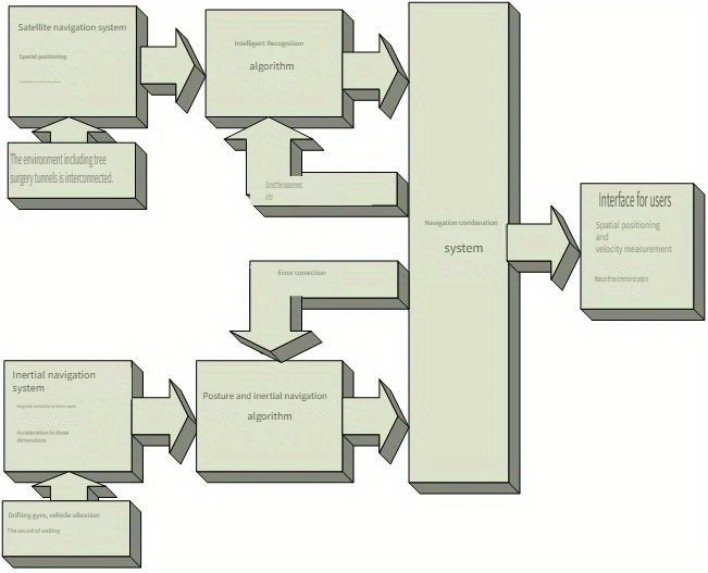
2.2 Product System Introduction
2.2.1 Satellite Navigation System:
The satellite navigation system has the advantages of global, all-weather and high-precision navigation. However, the satellite navigation system is easily affected by the surrounding environment, such as trees and buildings, resulting in multi-path effect, which reduces the accuracy of positioning results or even loses, especially in indoor environments such as tunnels, satellite navigation systems are basically unusable. In addition, even in the urban canyon or open environment, when the carrier speed is very low, the satellite navigation system will obtain the carrier azimuth information (course Angle) will produce a large drift error.
2.2.2 Inertial Navigation System:
Inertial navigation is based on Newton's laws of mechanics. By measuring the acceleration of the carrier in the inertial reference frame, integrating it with time, and transforming it into the navigation coordinates, information such as speed, yaw Angle and position can be obtained in the navigation coordinates, and carrier information of the carrier can be obtained at the same time. However, due to the serious gyroscope zero drift, vehicle vibration and other factors, the inertial navigation system cannot obtain high-precision orientation and speed information through direct integral acceleration, that is, the existing micro-inertial navigation system is difficult to work independently for a long time.
2.2.3 Integrated Navigation System:
Satellite/inertial integrated navigation makes full use of the advantages of inertial navigation system and satellite navigation system, and combines the two navigation algorithms based on the optimal estimation algorithm-Kalman filter algorithm to obtain the best navigation results. Especially when the satellite navigation system cannot work, the inertial navigation system is used to make the navigation system continue to work, ensure the normal work of the navigation system, and improve the stability and reliability of the system.
2.2.4 Odometer (Yes/no) input
The DR Scheme of the gyroscope of the conventional vehicle navigation system is often to achieve high-precision navigation and positioning in the complex environment of the car with odometer data input. The CE-GM-AGDR8639 system has odometer data input, which will obtain better high-precision positioning performance indicators.
For many automotive afterfitting markets, connectivity is complex and involves vehicle safety issues. The CE-GM-AGDR8639 system, without odometer input, can also achieve high-precision positioning, speed measurement and attitude measurement over a long period of time, and its performance has been greatly improved compared with existing related products on the market.
2.2.5 Vehicle attitude Angle
The CE-GM-AGDR8639 navigation system uses many years of research experience on MEMS inertial devices, and realizes the filtering of gyroscope drift and acceleration vibration signals through adaptive filtering algorithm, and further obtains high-precision attitude information, so as to meet various requirements of vehicle monitoring and navigation applications such as ramp detection.
2.2.6 Navigation System
CE-GM-AGDR8639 navigation system proposes an intelligent recognition algorithm for satellite navigation accuracy, which identifies the positioning accuracy of satellite navigation based on high-precision navigation information provided by integrated navigation. If the satellite navigation accuracy is good, integrated navigation will be carried out. Once the satellite navigation signal is very poor or even lost, it will automatically cut into the inertial navigation mode. In short, the CE-GM-AGDR8639 navigation system realizes the autonomous switching of integrated navigation and inertial navigation.
2.3 Product Features
2.3.1 Maximum parameter
Parameter | Index | Unit |
| Power source | ||
| Power supply voltage | 5.0V | V |
| environment | ||
| Operating temperature | -40°C to +85°C | °C |
| Storage temperature | -55°C to +100°C | °C |
2.3.2 Electrical characteristics
Parameter | Index | Unit |
Electric | ||
| Input voltage Vdd | 3.3~5.5 | V |
Electricity | 120 | mA |
| Power dissipation | 360 | mW |
Time | ||
| Time when the first valid data is powered on | <30 | mW |
2.4 Performance Specifications
2.4.1 There is mileage timing
| GNSS signal loss time | Receiver positioning mode | Horizontal position 1 | Horizontal velocity 1 | Pitch roll Angle 1 | Course Angle 1 |
| 5 s | standard setting | 1.0-2.0m | 0.05m/s | 0.3deg | 1.0 |
| 10 s | standard setting | 1.5-5.5m | N/A | N/A | N/A |
| 30 s | standard setting | 3.0m | N/A | N/A | N/A |
| 60 s | standard setting | 5.0m | 0.30m/s | 0.4deg | 1.0deg |
2.4.2 No Mileage timing
| GNSS signal loss time | Receiver positioning mode | Horizontal position 1 | Horizontal velocity 1 | Pitch roll Angle 1 | |
| 5 s | standard setting | 2.0-3.5m | 0.05m/s | 0.5deg | 1.0 |
| 10 s | standard setting | 10.0m | N/A | N/A | N/A |
| 60 s | standard settin | 25.0m | N/A | N/A | N/A |
| 120 s | standard setting | 60.0m | 0.5m/s | 1.0deg | 2.0deg |
* No odometer means OBD RX no vehicle data protocol input.
3. Size and pin definition
3.1 Product size:
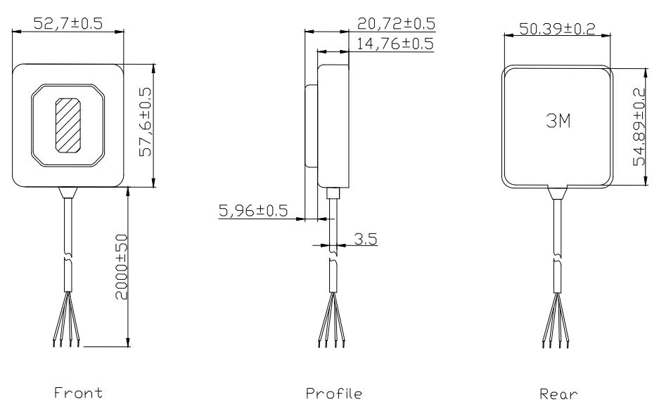
3.2 Pin Definition
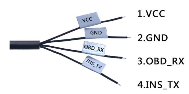
3.3 Connection definition table
| Pin number | Pin name | I/O | Describe | Remark |
| 1 | VCC | I | Power input | Input voltage: 3.3V~5.5V |
| 2 | GND | G | electrically | |
| 3 | OBD_RX | I | Vehicle speed protocol input | The default value is 9600bps |
| 4 | INS_TX | O | Inertial derivative data output |
4. Installation orientation
4.1 Installation Orientation
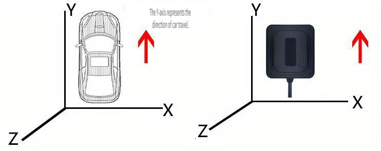
CE-GM-AGDR8639 installation method is shown in Figure 4. The installation Angle is strictly limited. Install CE-GM-AGDR8639 by referring to the direction of the arrow label on the cover
4.2 Installation Description
4.2.1 Modules must be installed before power-on. To ensure the operation effect, do not move modules during power-on.
4.2.2 During product design and installation, if only the inertial navigation function is applied, it can be installed and used in any position, and there is no special requirement on the installation of heading Angle, pitch Angle and roll Angle; If the vehicle attitude and driving behavior analysis function is to be applied, the module heading Angle should be consistent with the vehicle driving direction (schematic diagram), the pitch Angle can be installed and used within plus or minus 90 degrees, and the roll Angle can be installed and used within plus or minus 180 degrees (schematic diagram).
4.2.3 Limitation of use: This product is only suitable for vehicle (acceleration less than 2g), requiring rigid connection.
5. Instructions:
5.1 Sensor Calibration
Due to chip manufacturing process and other problems, the zero point, sensitivity and temperature drift parameters of each CE-GM-AGDR8639 sensor component (three-axis gyroscope, three-axis accelerometer) are different. In order to achieve the same performance indicators for each CE-GM-AGDR8639, Various error compensation has been carried out on various sensor components of CE-GM-AGDR8639 before delivery.
The sensor element calibration parameters of each product are not the same, if the same parameters are used, it will cause a large navigation error, this uniqueness can be used to prevent system piracy, thereby improving the reliability of user products.
5.2 Communication Ports
Communication serial ports do not provide hardware handshake mode and use 8-bit data bit, 0-bit parity check bit, and 1-bit stop bit (8-N-1). The default baud rate is 9600bps. You can change it to 115200bps based on user requirements.
5.3 Communication Frequency
Currently, the system supports a data refresh frequency ranging from 1HZ to 5HZ, and the default frequency is 3HZ.
5.4 Inertial navigation positioning accuracy
5.4.1 Angle error:
Horizontal straight line driving 1km, the average Angle deviation is not more than 2 degrees;
Slope and bumpy road straight driving 1km, the average Angle deviation is not more than 3 degrees;
For roundabout islands within a radius of 50m, the average angular deviation of a circle is not more than 5 degrees;
For roundabout islands with a radius of more than 50m, the average angular deviation of a circle is not more than 6 degrees;
4 consecutive 90-degree left turns or 4 consecutive 90-degree right turns with an average angular deviation of no more than 9 degrees.
5.4.2 Driving distance error:
The average error of the vehicle speed factor after calibration should not exceed 3‰
5.4.3 The endurance test of inertial navigation is greater than 1 hour
There is an inertial navigation product that matches the map. In the absence of GPS signal, the positioning of the inertial navigation is consistent with the location of the actual vehicle displayed on the map, and the duration is greater than 1 hour.
6. Inertial Navigation Data Protocol
6.1 Enter the Vehicle speed protocol
The speed value is transmitted to the inertial navigation system through the serial port, and the data format is:
$GPOBD,00009100, 009.28, 1 \r\n
Instructions:
Protocol name: $GPOBD.
Time slice: 00000100,100 ms accumulates 1 time; The next time is 00000200, and the time slice accumulates to 99999900.
Vehicle speed: 009.28 corresponds to 9.28Km/ h, accurate to two decimal places. Reverse signal: 0 for forward, 1 for reverse.
\r\n: return line feed.
Baud rate: 9600bps
Transfer rate:
The CAN line in OBD CAN BUS is output at a frequency of 10Hz, that is, the speed data is transmitted 10 times per second;
The K line is output at the frequency of 3Hz, because the K line communicates the actual speed three times per second, the 3Hz signal can be simulated to 10Hz output.
6.2 Inertial Navigation Output Data Protocol:
$GYRO, 01927300114, 03.67431, 2234.36541, 163.1, 52.80, 57.60, 168.4, and 12,3,0.011, 0.022, 0.985, 17200011185, 2.5, 0.6, 0.0, 4 G * 0
HEAD | STRING | $GYRO |
Time slice | LONG | Timestamp form, a total of eight digits, such as: 01927300, 1927 seconds 300 milliseconds |
longitude | DOUBLE | ddmm.mmmm degree division format, longitude value in degrees |
latitude | DOUBLE | ddmm.mmmm Degree division format, latitude value in degrees |
Altitude | DOUBLE | Altitude (-9999.9~99999.9), in meters (M) |
OBD velocity | DOUBLE | The unit is KM/H, accurate to two decimal places |
GPS speed | DOUBL | The unit is KM/H, accurate to two decimal places |
Course Angle | DOUBLE | 0-359, true north is 0, clockwise, accurate to 0.1 degrees |
Pitch Angle | DOUBLE | 0-900-900-0; Unit 0.1 degree; The actual Angle is divided by 10 |
Rolling Angle | DOUBLE | 0-1800-1800-0; Unit 0.1 degree; The actual Angle is divided by 10 |
X acceleration of gravity | DOUBLE | The unit G, |
Y acceleration of gravity | DOUBLE | The unit G, |
Z acceleration of gravity | DOUBLE | The unit G, |
Number of stars Received | INT | Number of satellites in use for resolving positions (00~99) |
Custom time | LONG | yymmddhhmmss (mm year yy month dd day hh hour mm minute ss second) format |
X angular velocity | DOUBLE | Unit: radians per second |
Y angular velocity | DOUBLE | Unit: radians per second |
Z angular velocity | DOUBLE | Unit: radians per second |
Tail | STRING | The first character is G or I (G is the GPS operating mode, I is the INS INS inertial guide) Working mode); The second character is *, and the next two characters are check codes. The verification code has the same rules as the GPS verification code. |
Copyright notice
The copyright of this user manual is owned by the Company and protected by the copyright Law of the People's Republic of China and other relevant laws. Without written permission, the Company shall not extract, copy, publish, collect, in whole or in part, the contents of this user manual of the Company for any purpose or disseminate any contents of this manual to the public by any means (electronic, printed, etc.). Otherwise, VLG will hold the infringer responsible for damaging the interests of the copyright owner.
The Company reserves the right to modify and improve the products described in this manual without prior notice, and reserves the right to modify or withdraw this manual at any time. If there is any ambiguity about the content of the user manual, please consult our company, agent or retailer.
The materials are provided without warranties of any kind, whether express or implied, with respect to loss, merchantability, or infringement of any patent, copyright or other intellectual property rights, whether directly or indirectly caused by the sale or use of the product or for a particular purpose. In the event of such a problem, the Company will no longer guarantee the accuracy or completeness of the information, text, graphics or other items contained in these materials. The Company shall not be liable for any special, indirect, incidental or indirect damages, including but not limited to loss of revenue or loss of profits resulting from the use of these materials.
The product is not intended for use in medical, life support equipment, or applications involving death, personal injury, or potential risk in the event of a product malfunction that would result in serious loss of life or property.
Post time:2024-05-24
