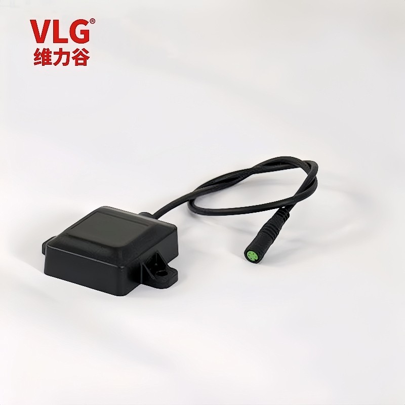
VLG-GM-AGDR8639/Dual-band GNSS+INS product technology
Product overview
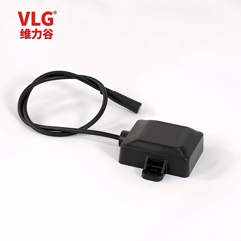
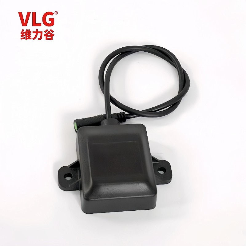
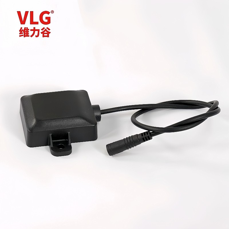
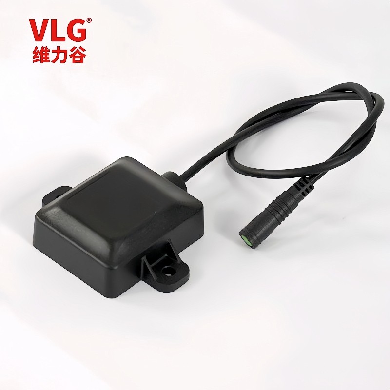
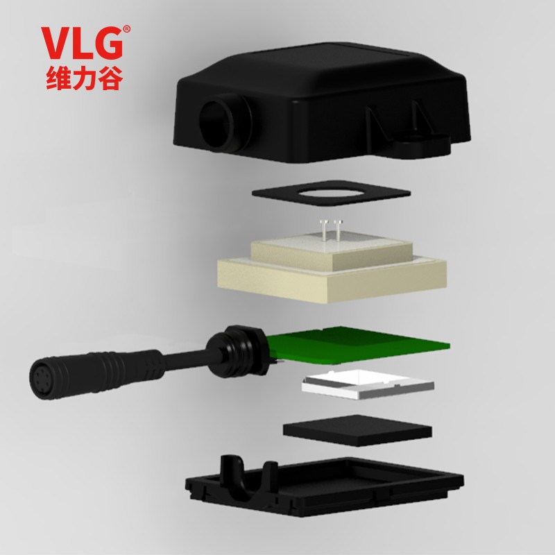
| CE-GM-AGDR8639 is a G-MOUSE product composed of MCU main control, MTK series dual-frequency multi-mode high-precision GNSS chip, six-axis gyroscope inertial system and dual-frequency antenna. CE-GM-AGDR8639 Built-in multi-positioning system concurrent receiver module, support GPS, GLONASS, Galileo, Beidou and QZSS L1&L5 band synchronous reception. It has 75 tracking channels and 135 acquisition channels, enabling it to capture and track any multi-satellite mixed signal; Compared with a single GPS system, the number of satellites can be significantly increased by the multi-positioning system, which greatly reduces the first positioning time, and can achieve stable and higher positioning accuracy and accuracy even when driving in complex urban environments. The six-axis gyroscopic inertial navigation system can continuously achieve high-precision positioning in the environment without satellite signals (tunnels, underground parking lots), filter out the high-precision positioning drift (dynamic and static) caused by occlusion, refraction and reflection of satellite signals in the city canyons and trees, and constantly output data information such as vehicle driving posture and drivers' dangerous driving behaviors |
|

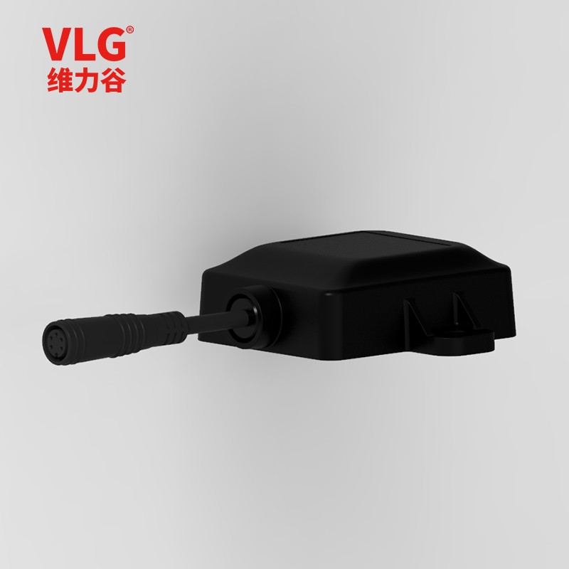
CE-GM-AGDR8639
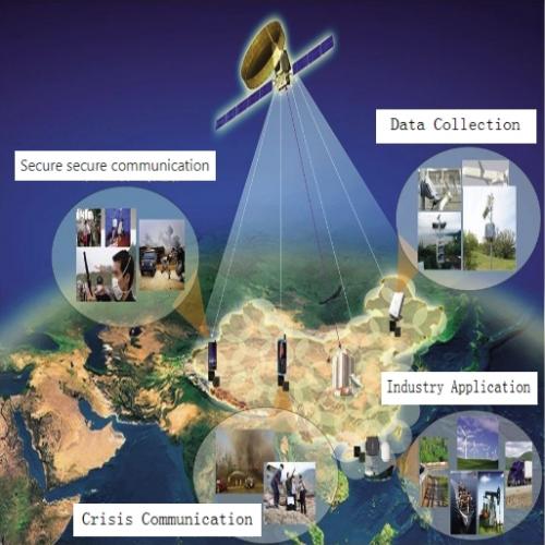
Product application
AGV robot
Agricultural automation equipment
High precision vehicle navigation
Bus intelligent transportation
Vehicle remote monitoring

product feature
| uses high performance low power dual-frequency GNSS chip | |
| Support for multiple satellite systems: GPS&QZSS,GLONASS, Galileo, Beidou, dual frequency L1&L5 signal synchronous reception | |
| Ultra-high tracking sensitivity: | -167dBm |
| Supported protocol | NMEA-0183& Custom Inertial Navigation Protocol |
| Built-in six-axis gyroscope and gravity acceleration sensor allows users to define a variety of Angle and gravity algorithms | |
| Supports autonomous inertial navigation and positioning without GNSS signals | |
| Built-in high gain low noise amplifier | improve the receiving sensitivity |
| Working voltage | 3.3V~5.5V |
| Power consumption | 120±5mA |
| Operating temperature | -40°C ~ +85°C |
| Patch antenna dimensions | 35X35X4mm+25X25X4mm |
| Product size | :52.7±0.5x57.6±0.5x20.72±0.5mm |
| Cable interface type | 4-core bare wire, cable length 200cm |
| Communication method | UART |
| Waterproof grade | IP67 |
| RoHS certified products | |
performance specification
1.1 Product Features
Item | Peculiarity | Item | Peculiarity |
Gyro drift | High precision attitude heading information is obtained by eliminating gyro drift | Component selection | High performance three axis gyroscope and three axis accelerometer |
Acceleration noise | Eliminate vibration acceleration and obtain high precision speed information | Error compensation | Complete orthogonal error/temperature drift and other error compensation |
Zero speed correction | Zero speed correction algorithm can prevent navigation data drift | Unique anti-theft | Each product calibration parameters are inconsistent anti-piracy |
Software algorithm | Adaptive extended Kalman filter algorithm | Waterproof class | Waterproof rating IP67 |
Intelligent recognition | Identify and isolate GNSS data with large errors | Communication protocol | Standard communication protocol NEMA-0183& Custom protocol |
odometer | Inertial navigation (with/without) speed input can achieve high-precision positioning, and inertial positioning will be more accurate with speed input | Engineering installation | Adjustable Angle fixed installation, easy to use |
| Navigation technique | Dual-frequency multi-mode positioning and autonomous switching of inertial navigation technology | Submeter level | Submeter localization in complex environments |
1.2 Technical Specifications
| parameter | specification |
| GNSS engine |
|
| GNSS signal |
|
Update frequency |
|
Positional accuracy |
|
Speed and time accuracy |
|
First positioning (TTFF) time |
|
| Sensitivity |
|
| GNSS operating limits |
|
Base level |
|
| UART port |
|
| Temperature range |
|
2. Product application
2.1 Product structure

2.2 Product System Introduction
2.2.1 Satellite Navigation System:
The satellite navigation system has the advantages of global, all-weather and high-precision navigation. However, the satellite navigation system is easily affected by the surrounding environment, such as trees and buildings, resulting in multi-path effect, which reduces the accuracy of positioning results or even loses, especially in indoor environments such as tunnels, satellite navigation systems are basically unusable. In addition, even in the urban canyon or open environment, when the carrier speed is very low, the satellite navigation system will obtain the carrier azimuth information (course Angle) will produce a large drift error.
2.2.2 Inertial Navigation System:
Inertial navigation is based on Newton's laws of mechanics. By measuring the acceleration of the carrier in the inertial reference frame, integrating it with time, and transforming it into the navigation coordinates, information such as speed, yaw Angle and position can be obtained in the navigation coordinates, and carrier information of the carrier can be obtained at the same time. However, due to the serious gyroscope zero drift, vehicle vibration and other factors, the inertial navigation system cannot obtain high-precision orientation and speed information through direct integral acceleration, that is, the existing micro-inertial navigation system is difficult to work independently for a long time.
2.2.3 Integrated Navigation System:
Satellite/inertial integrated navigation makes full use of the advantages of inertial navigation system and satellite navigation system, and combines the two navigation algorithms based on the optimal estimation algorithm-Kalman filter algorithm to obtain the best navigation results. Especially when the satellite navigation system cannot work, the inertial navigation system is used to make the navigation system continue to work, ensure the normal work of the navigation system, and improve the stability and reliability of the system.
2.2.4 Odometer (Yes/no) input
The DR Scheme of the gyroscope of the conventional vehicle navigation system is often to achieve high-precision navigation and positioning in the complex environment of the car with odometer data input. The CE-GM-AGDR8639 system has odometer data input, which will obtain better high-precision positioning performance indicators.
For many automotive afterfitting markets, connectivity is complex and involves vehicle safety issues. The CE-GM-AGDR8639 system, without odometer input, can also achieve high-precision positioning, speed measurement and attitude measurement over a long period of time, and its performance has been greatly improved compared with existing related products on the market.
2.2.5 Vehicle attitude Angle
The CE-GM-AGDR8639 navigation system uses many years of research experience on MEMS inertial devices, and realizes the filtering of gyroscope drift and acceleration vibration signals through adaptive filtering algorithm, and further obtains high-precision attitude information, so as to meet various requirements of vehicle monitoring and navigation applications such as ramp detection.
2.2.6 Navigation System
CE-GM-AGDR8639 navigation system proposes an intelligent recognition algorithm for satellite navigation accuracy, which identifies the positioning accuracy of satellite navigation based on high-precision navigation information provided by integrated navigation. If the satellite navigation accuracy is good, integrated navigation will be carried out. Once the satellite navigation signal is very poor or even lost, it will automatically cut into the inertial navigation mode. In short, the CE-GM-AGDR8639 navigation system realizes the autonomous switching of integrated navigation and inertial navigation.
2.3 Product Features
2.3.1 Maximum parameter
Parameter | Index | Unit |
| Power source | ||
| Power supply voltage | 5.0V | V |
| environment | ||
| Operating temperature | -40°C to +85°C | °C |
| Storage temperature | -55°C to +100°C | °C |
2.3.2 Electrical characteristics
Parameter | Index | Unit |
Electric | ||
| Input voltage Vdd | 3.3~5.5 | V |
Electricity | 120 | mA |
| Power dissipation | 360 | mW |
Time | ||
| Time when the first valid data is powered on | <30 | mW |
2.4 Performance Specifications
2.4.1 There is mileage timing
| GNSS signal loss time | Receiver positioning mode | Horizontal position 1 | Horizontal velocity 1 | Pitch roll Angle 1 | Course Angle 1 |
| 5 s | standard setting | 1.0-2.0m | 0.05m/s | 0.3deg | 1.0 |
| 10 s | standard setting | 1.5-5.5m | N/A | N/A | N/A |
| 30 s | standard setting | 3.0m | N/A | N/A | N/A |
| 60 s | standard setting | 5.0m | 0.30m/s | 0.4deg | 1.0deg |
2.4.2 No Mileage timing
| GNSS signal loss time | Receiver positioning mode | Horizontal position 1 | Horizontal velocity 1 | Pitch roll Angle 1 | |
| 5 s | standard setting | 2.0-3.5m | 0.05m/s | 0.5deg | 1.0 |
| 10 s | standard setting | 10.0m | N/A | N/A | N/A |
| 60 s | standard settin | 25.0m | N/A | N/A | N/A |
| 120 s | standard setting | 60.0m | 0.5m/s | 1.0deg | 2.0deg |
* No odometer means OBD RX no vehicle data protocol input.
3. Size and pin definition
3.1 Product size:

3.2 Pin Definition

3.3 Connection definition table
| Pin number | Pin name | I/O | Describe | Remark |
| 1 | VCC | I | Power input | Input voltage: 3.3V~5.5V |
| 2 | GND | G | electrically | |
| 3 | OBD_RX | I | Vehicle speed protocol input | The default value is 9600bps |
| 4 | INS_TX | O | Inertial derivative data output |
4. Installation orientation
4.1 Installation Orientation
CE-GM-AGDR8639 installation method is shown in Figure 4. The installation Angle is strictly limited. Install CE-GM-AGDR8639 by referring to the direction of the arrow label on the cover

<span style=